EFA CAMverse › DXF viewer
NewPrepare DXF and pass it on cleanly→ Format guide · DXFReceived an outline, rout contour or front panel as .dxf? EFA CAMverse opens DXF drawings natively – no cloud upload –, shows them right next to the PCB data of the same project and passes them on, prepared, as DXF.
DXF – the de-facto standard for mechanical geometry (AutoCAD).
DXF (“Drawing Interchange Format”) is a CAD exchange format defined by Autodesk. It describes geometric drawing elements – lines, arcs, circles, polylines, splines, texts, hatches and blocks – via a group-code based ASCII schema. Introduced in 1982 with AutoCAD 1.0, it has been a cross-industry de-facto standard ever since.
In the PCB and assembly world, DXF mainly serves mechanics: board outline, rout contours, cutouts, panel mechanics and front panels – the exchange with mechanical CAD/CAM. DXF has no PCB intelligence such as nets or components.
Download for free and install – a native Windows application (10/11, 64-bit), free to use as a viewer.
Open the drawing directly – ASCII DXF is read; the unit is taken from the file. Binary DXF is not loaded (save as ASCII DXF in your CAD).
Review contours, measure distances – and view the drawing next to the Gerber or ODB++ data of the same project.

All common drawing elements – lines, arcs, circles, polylines, splines, texts, faces, hatches and dimensions.
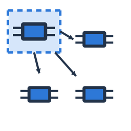
Blocks – nested ones too – appear in the right place.

The unit comes from the file – measure distances and contours right in the drawing.
Open the mechanical drawing next to the PCB data of the same project – align outline and layout in the same tool.
Output the view as PDF, PNG or JPG – for documentation and coordination.

A native Windows application – no cloud, no upload. Your drawings stay on your machine.
A DXF file from your customer or from design is rarely usable as it is. EFA CAMverse prepares it and passes it on – as DXF for depaneling, design and documentation.
DXF source file.dxfCombine with the PCB dataEFA CAMverse opens different formats of the same project in one interface – the DXF mechanics next to Gerber, ODB++ or KiCad. Check rout contours against the layout, align the front panel with the assembly: one tool, one way of working. Why one tool →
Output & documentOutput views as PDF, PNG or JPG – for manufacturing documents, customer queries or internal coordination. Passing on as DXF →
ASCII, binary and DWGDXF is versioned along AutoCAD releases (R12 … 2018) and exists in ASCII and binary form – EFA CAMverse reads the ASCII form; binary DXF is rejected. The related DWG is AutoCAD's native format and not the same thing: simply save as ASCII DXF in your CAD.
DXF in the PCB worldDXF knows only drawing geometry – no nets, layer roles, padstacks or components. It comes from the mechanical CAD world and complements the electronics formats: EFA CAMverse treats it accordingly as a pure geometry format next to Gerber, ODB++ & co. To the Gerber guide →
And when the next customer delivers something else: EFA CAMverse also opens 8 more PCB/CAM formats – in the same tool, with the same way of working.
EFA CAMverse is free to use as a viewer – unlock advanced features whenever you need them. Native on Windows, your data stays local.
EFA CAMverse 2026 · free viewer · Windows 10/11 · 64-bit
 EAGLE
EAGLE ODB++
ODB++ IPC-2581
 GenCAD
 IPC-D-356
 PADS
PADS KiCad
KiCad