EFA CAMverse › DXF export
NewDXF export from all 9 formats→ Topic guide · DXF exportDepaneling software needs the outline and milling channels, mechanical design needs drill holes and component outlines, documentation needs every layer. EFA CAMverse creates the right DXF file from Gerber, ODB++, IPC-2581, KiCad and 5 more formats – with ready-made settings for each purpose.






 DXF.dxf
You choose what the file is for; EFA CAMverse puts the right content together. Before saving, a summary shows you what the file will contain.
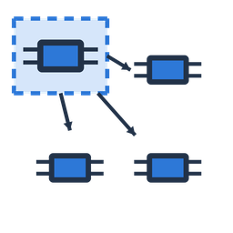
For the depaneling software
Lean geometry for router and saw – without filled areas and blocks.
For the CAD program
The same geometry for fixture, enclosure or test adapter – plus filled areas and blocks.

For drawings and archive
The complete board as a drawing – every layer on its own DXF layer.
Every preset can be adjusted: add or remove content item by item – EFA CAMverse remembers your settings per purpose, and one click restores the preset.
Open a Gerber set with drill data, an ODB++ package, a KiCad project or one of the other formats in EFA CAMverse – as usual.
Start the DXF export in the “Tools” tab and choose depaneling, mechanical design or documentation – refine it under “Customize” if needed.
Save one DXF file or one file per layer. A report lists anything noteworthy such as open contours; a single file can then be opened and checked right away.
A DXF file is only as good as the next program's ability to read it. That is why EFA CAMverse takes care of clean geometry and clear layers.
Contents of the DXF file (excerpt)Adapt layer names and colours with a layer profile.
The DXF export works with every format EFA CAMverse opens. What ends up in the file depends on what the source data provides.
Outline from the outline layer, drill holes from the drill data. If there is no outline layer, you get a marked substitute outline and a note in the report.
To the format page →Outline, drill holes and components – for panels, every board at its position.
To the format page →Outline, drill holes and components – for panels, every board at its position.
To the format page →Outline, drill holes and components straight from the board – no detour via Gerber.
To the format page →Outline, drill holes and components straight from the board – no detour via Gerber.
To the format page →Outline, drill holes and components straight from the ASCII export – no detour via Gerber.
To the format page →Outline, drill holes and components – including panel descriptions with every board.
To the format page →Drill holes and tooling holes; the pads of the test netlist with the “All board layers” option. This source provides no outline.
To the format page →Prepare drawings from other programs: assign layers to outline, drill holes or fiducials once – EFA CAMverse remembers this per layer name; texts keep their style.
To the format page →How do I convert Gerber to DXF?Open the Gerber set with drill data, choose the DXF export in the “Tools” tab, select the purpose and save. The outline comes from the outline layer; if there is none, you get a marked substitute outline and a note in the report.
ODB++ or IPC-2581 as DXF – panels too?Yes. For panels, EFA CAMverse outputs every board at its position – or one board plus a position list. This also applies to panels from GenCAD.
Which DXF version, which unit?The default is DXF 2000 in millimetres. Choose DXF R12 for older programs and inches for inch-based environments. Filled areas and blocks are only available in DXF 2000.
 What happens to open contours?
EFA CAMverse closes small gaps automatically. Whatever stays open goes onto a layer of its own and is listed in the report – so you see at once where the source data needs fixing.
 Is the DXF export free?
EFA CAMverse is free to use as a viewer. The DXF export is one of the advanced features you unlock whenever you need them.
And for test and pick-and-place?For that, EFA CAMverse passes the data on as GenCAD 1.4 – from 7 of the 9 formats. Create GenCAD →
EFA CAMverse is free to use as a viewer – unlock advanced features such as the DXF export whenever you need them. Native on Windows, your data stays local.
EFA CAMverse 2026 · free viewer · Windows 10/11 · 64-bit